

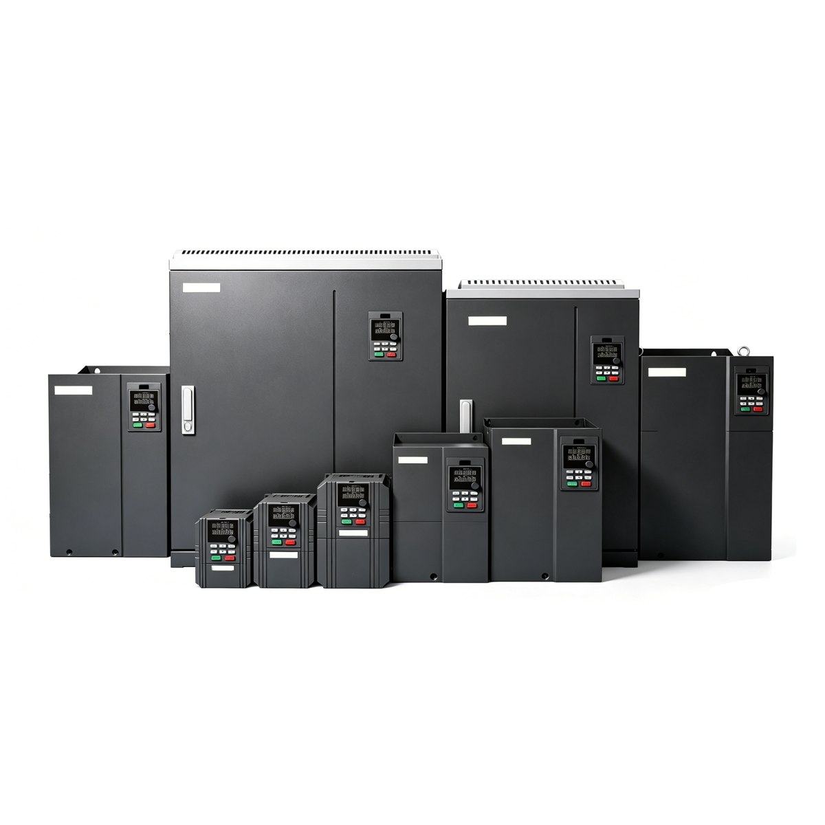
D110 & CD110S Series General Purpose Vector Control Inverter
Basic Document Info
Version: V1.0
Remark: Brochure information may be subject to change without prior notice
Model: CD110 Series / CD110S Series
Product Type: General Purpose Vector Control Inverter
Brand Location: Shenzhen (Silicon Valley of China)
2. Company Profile
High-tech enterprise focusing on R&D, production and sales of VFD and servo drives.
R&D team accounts for 35% of total employees; core team has 20 years industry experience.
Own multiple patents in low speed high torque & synchronous high speed motor control.
Customer-centric & market-oriented; support customized products and solutions.
Complete supply chain & production system: pre-processing, assembly line, automatic test platform, temperature aging room, etc.
14 domestic offices & after-sales centers, nationwide sales network.
3. Product Introduction
CD110: Adopts sensorless vector control (SVC), excellent asynchronous motor drive performance, rich hardware & software functions, high usability and reliability.
CD110S: Support driving synchronous motor; CD110 only for asynchronous motor.
4. Product Core Features
4.1 Control Performance
SVC control mode; support static & rotary motor parameter autotuning.
4.2 Structure & Installation
Miniaturized size, save installation space.
Mounting methods:
≤380V 2.2kW: Rail mounting & wall mounting
≥380V 4.0kW: Wall mounting & flange mounting
Fan with independent disassembly design, easy maintenance.
4.3 Interface & Configuration
Standard built-in RS485 communication port.
Rich I/O terminals + external keypad interface.
Brake Unit Configuration
380V: ≤30kW built-in brake unit standard; 37~110kW optional; ≥132kW external required
660V: All models need external brake unit
4.4 Built-in Functions
Simple PLC, multi-step control, built-in PID, torque control, multi-point V/F curve, energy consumption brake, magnetic flux brake, DC brake, instantaneous non-stop running.
4.5 Keypad
Standard external ordinary LED keypad; optional LCD keypad.
Support parameter copy, upload & download for batch debugging.
4.6 Application Industry
Food, plastics, ceramics, petroleum, cables, air compressors, machine tools, woodworking, textiles, printing & packaging, chemicals, environmental protection, fans & pumps, etc.
Excellent Performance Description
Motor Parameter Autotuning
Rotary autotuning: Load decouplable, high precision requirement
Static autotuning: Load non-decouplable, ordinary precision requirement
Stall Control
Overcurrent stall: Adjust frequency during acceleration to avoid overcurrent
Overvoltage stall: Adjust frequency during deceleration to avoid DC bus overvoltage
Multiple Braking Modes
| Braking Type | Feature | Applicable Scene |
|—-|—-|—-|
| Energy consumption brake | Large brake torque, fast speed; need brake unit/resistor | Frequent braking with large inertial load |
| Magnetic flux brake | No extra unit/resistor; fast stop | Occasional braking; not for frequent large inertial braking |
| DC brake | No extra unit/resistor; keep torque after stop | Brake then free run; keep torque at zero speed |
Instantaneous Power Failure Non-stop
Keep running by motor feedback energy during grid voltage drop; suitable for textile, chemical fiber and continuous production occasions.
High Frequency Operation
Stable current waveform under vector control at 200Hz / 400Hz; well-controlled voltage & current, reduce fault rate.
6. Reliability & Quality
Comply with IEC international standards, passed CE certification, IP20 protection.
Advanced thermal simulation & full load/overload thermal test, strict derating standard.
Wide Voltage Range
Rated voltage: AC 380~480V
Allow fluctuation: 320~528V
Unbalance degree: <3%
Output frequency range: 0~500Hz
Complete test system:
EMC Test: CS/CE, RS/RE, EFT, lightning surge, voltage drop, harmonic test etc.
Environment Test: Salt spray, high/low temp, thermal shock, vibration, drop, aging etc.
General Test: Short-circuit, temperature rise, overload, overvoltage/undervoltage protection, efficiency test etc.
7. Technical Parameters
7.1 Input & Output
Input Voltage: 1PH 220VAC±15%; 3PH 380VAC±15%
Input Frequency: 50/60Hz ±5%
Output Voltage: 0 ~ Input voltage
Output Frequency: 0 ~ 500Hz
Overload Capacity (G type):
150% 1min; 180% 3s; 200% 0.5s
7.2 Control Performance
Item SVC V/F
Control mode Sensorless vector V/F
Starting torque 150% @0.25Hz 150% @0.5Hz
Speed regulation range 1:200 1:100
Speed control accuracy ±0.5% ±0.1%
Torque response time ≤40ms ≤100ms
Modulation SVPWM —
7.3 Basic Function Parameters
Start frequency: 0.00~10.00Hz
ACC/DEC time: 0.1~65000.0s
Carrier frequency: 0.5kHz~16.0kHz
Frequency setting: UP/DOWN, digital, analog, multi-step, PID, MODBUS communication
Start mode: Start from start frequency / DC braking restart / speed tracking restart
Stop mode: Decelerate to stop / coast to stop / decelerate + DC brake
DC brake: Start frequency 0~max freq; time 0.01~36s; current 0~100% rated
Support automatic voltage regulation, transient frequency drop, torque boost, multi V/F curve, linear/S-curve ACC/DEC, max 16-step simple PLC running.
7.4 Control Terminal Configuration
Digital Input: 8 channels (1 can be HDI high speed pulse input)
Analog Input: 2 channels AI1/AI2, 0~10V / 0~20mA optional
Digital Output: 2 open collector (1 can be HDO high speed pulse output)
Analog Output: 2 channels AO1/AO2, 0~10V / 0~20mA optional
Relay Output: 2 groups
Communication: RS485, support Modbus-RTU
7.5 Keypad & Display
Dual-row 5-bit LED display; monitor two sets of parameters simultaneously
Parameter copy upload/download, key lock function
Real-time monitoring: output freq/current/voltage, bus voltage, motor speed, PID etc.
7.6 Protection Functions
Accelerate/decelerate/constant speed overcurrent & overvoltage, bus undervoltage, motor/inverter overload, input/output phase loss, module overheat, external fault, communication fault, short circuit to ground/phase to phase etc.
7.7 Environment Condition
Installation: Indoor, altitude<1000m, no corrosive/flammable gas, dust, oil mist
Ambient temp: -10~40℃; 40~50℃ derate 1%/℃
Humidity: 5%~95% non-condensation
Altitude: 0~2000m; above 1000m derate 1%/100m
Vibration: <0.5g
Storage temp: -40~70℃
8. Model Coding Rule
Format: CD110-2R2G-4-B
Series: CD110
Rated Power: 2R2=2.2kW
Load Type: G = Constant torque load
Voltage Class: 2S=1PH220V; 4=3PH380V; 6=3PH660V
Brake Unit: B = Built-in brake unit
9. Product Ratings Parameter Table
Contain full models:
1PH 220V(2S): 0.75kW~2.2kW
3PH 380V(4): 0.75kW~1000kW
3PH 660V(6): 22kW~1250kW
Each model includes: Voltage class, Rated power(kW), Input current(A), Output current(A), Suitable motor(kW)
10. Wiring & Dimension
10.1 Wiring Diagram
Main circuit & control circuit terminals: PE, P1, PB, DI1~DI7, HDI, DO1, HDO, AI1/AI2, AO1/AO2, Relay output, RS485+, RS485-, +24V, COM etc.
10.2 Frame Division
Frame A: 0.75~5.5kW 380V
Frame B: 7.5~15kW 380V
Frame C: 18.5~160kW 380V / 22~185kW 660V
Frame D: 185~450kW 380V / 200~500kW 660V
Frame E: 500~1000kW 380V / 560~1250kW 660V
10.3 Keypad Dimension
Mounting hole size: 80.4×140mm
Connect by ordinary network cable, max distance ≤50m
10.4 Inverter Dimension
Overall size W/H/D, mounting hole, weight(kg) for all frames (unit:mm).
11. Optional Accessories
External LED/LCD keypad (with parameter copy function optional)
Reactor: Input reactor, Output reactor
Filter: Input filter, Output filter
Brake unit & brake resistor
12. Picture & Diagram Description
Document contains schematic diagrams only:
Wiring diagram
Keypad dimension schematic
Inverter frame dimension schematic
No independent picture files; all dimension & wiring refer to schematic and parameter table.
Reviews
There are no reviews yet.