

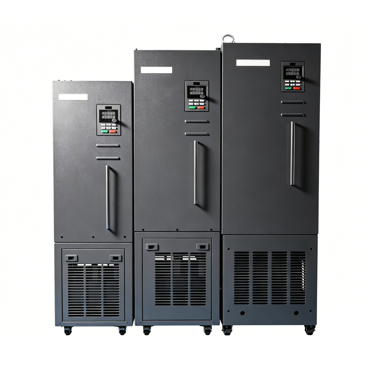
CD580 & CD580S Series High Performance Vector Control Inverter
Basic Document Information
- Product Series:CD580 Series / CD580S Series
- Product Type:High Performance Vector Control Inverter
- Version:V1.0
- Company:Shenzhen Xinjuyuan Technology Co., Ltd
- Location:Shenzhen (Silicon Valley of China)
2. Company Profile
- High-tech enterprise specialized in R&D, production and sales of VFD and servo drives for industrial control.
- R&D team accounts for 35% of total employees; core members own 20 years of industry technical & management experience.
- Possess multiple patents in low speed high torque and synchronous high speed motor control.
- Customer-oriented, support customized products and system solutions.
- Complete intelligent production system: pre-processing, assembly line, automatic test platform, temperature aging room, etc.
- 14 national offices & after-sales centers, full-coverage sales service network across China.
3. Product Introduction
- New hardware & software high-performance platform design.
- Support both asynchronous motor and permanent magnet synchronous motor.
- Integrate torque control & speed control, stable operation under complex working conditions.
- Built-in rich application macros:PID, multi-pump control, constant pressure water supply etc.
- Independent air duct design + PCB three-proof coating, improve environmental adaptability.
4. Core Product Features
4.1 Control Platform & Motor Adaptation
- New generation vector control algorithm platform.
- CD580: Asynchronous motor, open-loop / closed-loop control.
- CD580S: Permanent magnet synchronous motor, open-loop / closed-loop control.
- Independent core algorithm, accurate torque & excitation decoupling, fast dynamic response.
4.2 Structural Design
- Book-type narrow body design, save installation cabinet space greatly.
- Independent air duct + full DC fan cooling system, safe and reliable heat dissipation.
- Complete thermal simulation optimization, reasonable hardware layout.
- Modular hardware & software design, strong expandability.
- PCB sprayed with three-proof paint, whole machine three-proof design for high stability.
4.3 Keypad & Interface
- Optimized keypad design; optional new dual-display external keypad.
- Rich expansion interfaces and optional accessories for diverse applications.
4.4 Industry Application
Textiles, Ceramics, Woodworking, Grinders, Cables, Food, CNC, Chemicals, Plastics, Petroleum, Fans & Pumps.
Performance Characteristics
5.1 Multi-Motor Compatibility
Support ordinary asynchronous motor, variable frequency motor, AC asynchronous servo motor, permanent magnet synchronous motor, high-speed motor, motor spindle.
5.2 Current & Torque Limit
Software current limit and torque limit, effectively suppress impulse current in CNC, brick machine and sudden load change occasions.
5.3 Motor Parameter Autotuning
- Rotary autotuning: For decouplable load, high control accuracy requirement.
- Static autotuning: For non-decouplable load, ordinary accuracy requirement.
Accurately identify motor parameters, easy debugging, high precision and fast response.
5.4 Overvoltage Suppression
Adjust running frequency and ACC/DEC time without brake unit/resistor; suppress DC bus voltage rise, avoid overvoltage alarm for oilfield pumping units, punching machines.
5.5 Low Frequency High Torque
- Starting torque: SVC 150% @0.5Hz; FVC 180% @0.0Hz
- Torque control accuracy: ±5%
- Torque response time: ≤40ms
5.6 Overexcitation Braking
Realize fast stop without extra brake resistor; suppress bus overvoltage during deceleration, improve operation stability.
6. Hardware & Structural Advantages
- Innovative book narrow structure: Take 2.2kW 380V as example, save cabinet space obviously.
- Isolated layout: Electronic components separated from radiator air duct; enhanced protection for capacitor, MOS tube and relay; fully sealed design for harsh environment.
- High-standard terminal blocks:
- Main circuit: IEC 60998-2-1 / UL 1059 standard barrier terminals, large current carrying capacity.
- Control circuit: IEC 998-2-1 / UL1059 / UL486E European terminals, 300V/10A, insulation DC500V/500MΩ.
- Three-phase full current detection: Fast vector response, output phase loss/imbalance protection, enhance motor short-circuit protection.
- Innovative short-circuit detection: Power-on ground short-circuit detection + running inter-phase short-circuit detection, immediate output blocking for protection.
- Wide voltage adaptability: Input voltage allow ±15% fluctuation, adapt to harsh power grid.
7. Technical Parameters
7.1 Input & Output
- Rated input voltage:1PH 220VAC±15%;3PH 380VAC±15%
- Rated input frequency:50/60Hz ±5%
- Output voltage:0 ~ Input voltage
- Output frequency:0 ~ 400Hz
- Overload capacity (G type):150% rated current 1min;180% 3s;200% 0.5s
7.2 Control Performance
| Item | SVC | V/F |
|---|---|---|
| Control mode | Sensorless vector | V/F control |
| Modulation | SVPWM | — |
| Starting torque | 150% @0.25Hz | 150% @0.5Hz |
| Speed regulation range | 1:200 | 1:100 |
| Speed control accuracy | ±0.5% | ±0.1% |
| Torque response time | ≤40ms | ≤100ms |
7.3 Basic Functions
- Carrier frequency:0.5kHz ~ 16.0kHz
- Start mode:Start from start frequency / DC braking restart / speed tracking restart
- Stop mode:Decelerate to stop / coast to stop / decelerate + DC brake
- Frequency setting:UP/DOWN, digital, analog, multi-step, PID, MODBUS communication
- Speed tracking restart: smooth non-impact start for rotating motor
- Built-in PID: easy closed-loop process control
- DC braking: start frequency 0~max freq; time 0.01~36s; current 0~100% rated
- V/F curve: linear, multi-point, square, V/F separation
- Simple PLC: max 16-step speed operation
- Overvoltage / Overcurrent stall control: automatic limit to avoid fault and ensure continuous running
7.4 Control Terminal Configuration
≤22kW Models
- Digital Input: 4 ordinary DI + 1 HDI (max 1kHz)
- Digital Output: 1 HDO + expandable 1 DO
- Analog Input: 1 AI (0~10V/0~20mA), expandable to 2AI
- Analog Output: 1 AO, expandable to 1AO
- Relay Output: 1 standard + 1 expandable
>22kW Models
- Digital Input: 8 DI (1 as HDI, max 50kHz)
- Digital Output: 2 collector outputs (1 as HDO)
- Analog Input: 2 AI (AI1:0~10V/0~20mA; AI2:-10~10V)
- Analog Output: 2 AO (0~10V/0~20mA optional)
- Relay Output: 2 relays (3A/AC250V, 1A/DC30V)
7.5 Expansion & Communication
- Expansion interface: support I/O card, PROFIBUS-DP card, PG encoder card, PT100/1000 card (only one card connected at a time)
- RS485: support Modbus-RTU
7.6 Protection Functions
Accelerate/decelerate/constant speed overcurrent & overvoltage, bus undervoltage, motor/inverter overload, input/output phase loss, module overheat, external fault, communication fault, ground short-circuit, phase-to-phase short-circuit, PID feedback disconnection etc.
7.7 Keypad & Display
- Dual-row 5-bit LED display, monitor two sets of inverter parameters simultaneously
- Parameter upload/download copy function
- Full/partial key lock to prevent misoperation
- Real-time monitoring: output frequency/current/voltage, bus voltage, motor speed, PID parameters, module temperature etc.
7.8 Environmental & Installation Conditions
- Application site: Indoor, altitude<1000m, no direct sunlight, dust, corrosive/flammable gas, oil mist, water, salt
- Ambient temperature:-10~40℃;40~50℃ derate 1% per ℃ rise
- Humidity:5%~95% non-condensation
- Altitude:0~2000m;above 1000m derate 1% per 100m rise
- Vibration:<0.5g
- Storage temperature:-40~70℃
- Mounting:Wall mounting / floor mounting
- Protection grade:≤160kW IP20;≥185kW IP00
8. Model Coding Rule
Format:CD580-2R2G-4-B-L1-O1
- Series: CD580 / CD580S
- Rated Power: 2R2=2.2kW
- Load Type: G = Constant torque load
- Voltage Class:
- 2S: 2PH AC220V
- 2: 3PH AC220V
- 4: 3PH AC380~480V
- 6: 3PH AC660~690V
- Brake Unit: B = Built-in brake unit
- Reactor: L1 = Built-in DC reactor (30~500kW optional)
- Expansion Card:
1=I/O card 2=PROFINET 3=PROFIBUS-DP 4=incremental PG 5=rotary encoder 6=sine-cosine encoder
9. Product Ratings Parameter Table (3PH 380V)
Contains model, voltage class, rated power(kW), input current(A), output current(A), applicable motor(kW)
Power range:0.75kW ~ 500kW
Note: Input current bracket data = value with DC reactor configured.
10. Wiring & Dimension
10.1 Wiring Diagram Type
- Type Ⅰ:≤22kW main circuit & control circuit wiring
- Type Ⅱ:≥30kW main circuit & control circuit wiring
Support DI sink/source mode; AI/AO analog voltage/current mode configurable by jumper/code switch.
10.2 Keypad Dimension
- Type Ⅰ keypad:for ≤22kW
- Type Ⅱ keypad:for ≥30kW
With external mounting hole size and bracket dimension data (unit:mm)
10.3 Inverter Frame Division
Frame A/B/C/D/E/F correspond to different power segment models, with/without base version optional.
10.4 Mounting Dimension
Complete wall mounting & floor mounting dimension table (unit:mm): overall size, mounting size, aperture, cabinet outline number.
11. Optional Accessories
- External LED/LCD Keypad (dual-row 5-bit display, LCD optional)
- I/O Expansion Card
- PG Encoder Expansion Card (max 200kHz)
- Profibus Communication Card
- Input / Output Filter
- Input / Output Reactor
12. Diagram & Illustration Note
Document contains only schematic drawings:
- Two types of inverter wiring diagrams
- Keypad structure & opening dimension schematic
- Inverter frame outline schematic
- Wall/floor mounting dimension table No independent picture files; all installation, wiring and dimension refer to schematic and parameter table.
Reviews
There are no reviews yet.